Additively manufactured (AM) materials usually suffer from high surface roughness as result their inherent manufacturing process. Affecting mainly fatigue life, this can be detrimental to overall materials and components performance. Moreover, removing the supports (and powder) used during manufacturing is time-consuming and can even be impossible in highly complex designs, especially with parts with internal features such as channels. This is typically the case in almost all metal AM processes.
The industry as a whole is aware of this issue and is developing solutions through a variety of approaches. One such approach is the Hirtisation® process which has been developed by Hirtenberger for the post-treatment of AM components to address the aforementioned AM constrains/issues. The method is based on a combination of electrochemical pulse methods, hydrodynamic flow and particle assisted chemical removal and surface treatment and has shown potential for the treatment of highly complex AM parts.
The objective of this feasibility study is to assess the effectiveness performance of the AM Hirtisation® treatment in decreasing the surface roughness and removing the manufactured supports without modifying any other properties of the samples. To evaluate these there are 3 sets of components that will be manufactured by MTC using laser powder bed fusion AM:
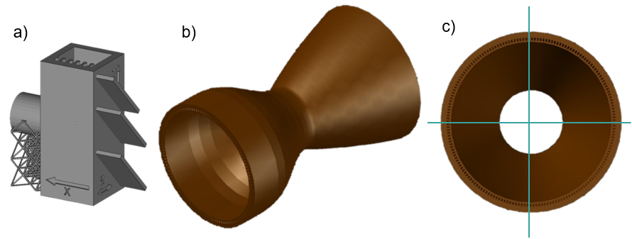
Figure 1 - a) AlSi10Mg artefact, b) In718 thrust chamber component c) Quarter segments
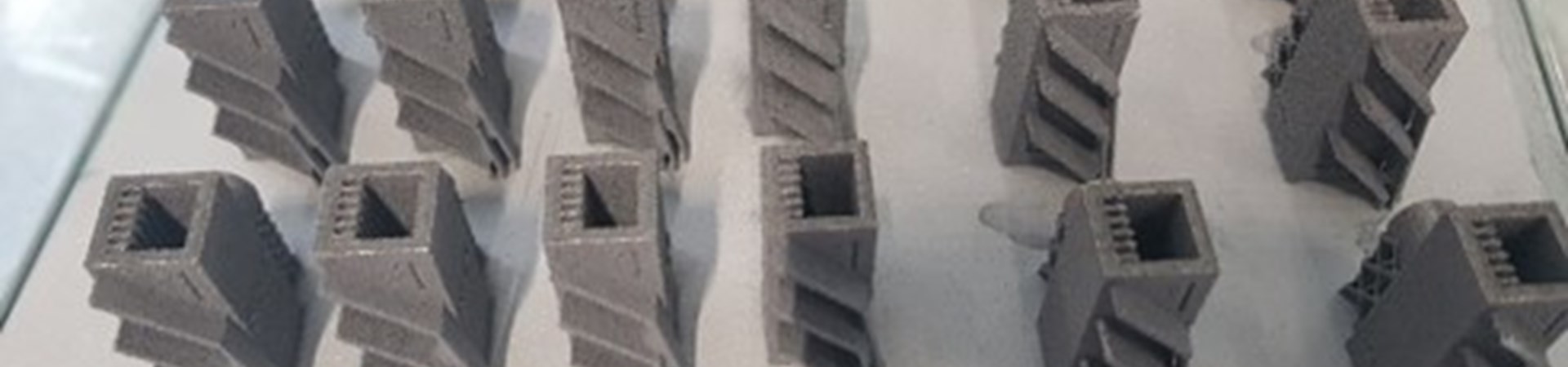
Some examples of parts manufactured for the aluminium artefact and the mechanical test specimens are shown in Figure 2. Due to the sensitivities of the machine in processing very fine lattice structures in the aluminium artefact, process parameter optimisation was required to achieve good quality parts. Also, due to the recoating forces experienced during the manufacture of the vertical mechanical test specimens in the M400 machine, stiffening structures were used.
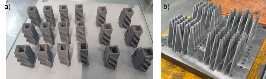
Figure 2 - a) Manufactured AlSi10Mg samples, and b) example build of In718 test specimens
To enable the thrust chamber component to be post-processed effectively using the Hirtisation process, some additional features were required to be designed and added to the part. This included a manifold to enable the flow of an electrolyte through the part for the electrochemical process to work effectively in the long channels as well as an electric connection plate to enable attachment of electrical connectors. In addition, some features were added to the base to aid removal of powder from the internal channels following completion of the build.
To reduce risk of build failure and to improve geometrical conformance, build simulation was carried out prior to the design finalisation (Figure 4). This highlighted some regions that required further consideration to reduce contact with the recoater blade.
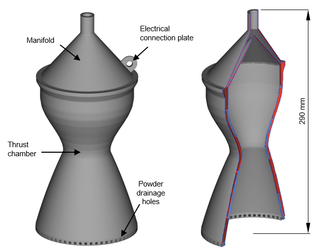
Figure 3 - Thrust chamber demonstrator part (and section view) with modifications to aid manufacture and post-processing
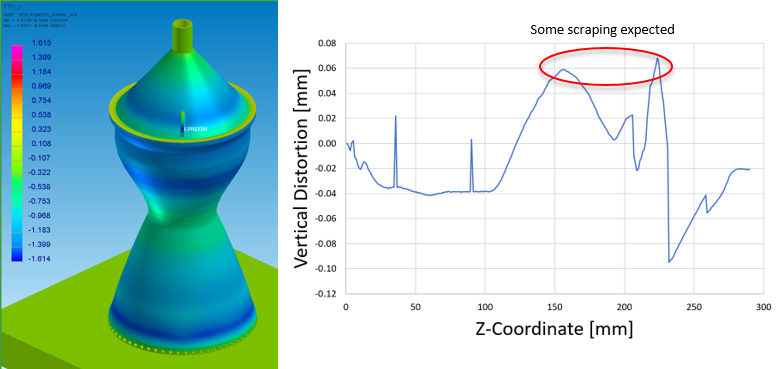
Figure 4 - Prediction of vertical distortion during build using ESI AM build simulation software
To enable trials to be conducted to optimise the post-processing route prior to the full component, a quarter version of the thrust chamber was designed as shown in Figure 5. Four of these quarters were then assembled together as shown in Figure 5 in preparation for building in the AM machine to avoid distortion issues, to be later separated using wire electrical discharge machining (EDM).
The features necessary to add to the thrust chamber demonstrate the importance of designing for post-processing as well as for the build itself. The results of the evaluation of the surface finishing techniques will enable further knowledge to designers of achievable surface finishing and geometric limitations.
The remaining work for this project is to finish the manufacture and post-processing of the mechanical test samples, and to manufacture the thrust chamber components, prior to the Hirtisation processing.
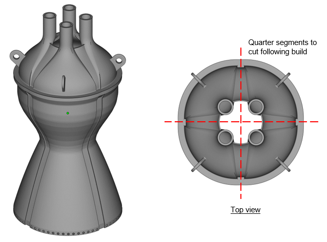
Figure 5 – Quarter test samples merged together for AM build to be separated following build through wire EDM
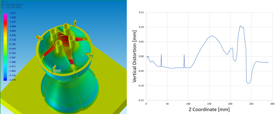
Figure 6 – Prediction of vertical distortion during build using ESI AM build simulation software