Propulsion filters are used in aerospace to enable the filtration of small particles (<50 µm) from large volumes of fluid being transported at high pressures. The current solutions for filtering down to such low filtrations rates include etched disk filters or wire mesh filters. The former of these is able to achieve good filtration rates over a large surface area but unfortunately suffers from being comparatively heavy because of poor material removal efficiency during the etching process. The latter of these suffers from movement of wire strands caused by particles damaging the surface thereby worsening the filtration rate over time. Furthermore, both of these solutions require that the filters be assembled from multiple components, which can be less time and cost efficient but can also result in component dislocation over time if they are not assembled well enough.
The advanced propulsion filter concept (Figure 1) was established by ESA in order to out-perform these existing technologies. By utilising additive manufacturing (AM), the filter can be manufactured from one component rather than several, can be produced in reduced manufacturing times and can be made at both a lower cost and a reduced mass. The key challenge when producing such a component by additive manufacturing is achieving the small pore sizes (<30 µm) required for the application. In order to achieve such a low pore size the technology utilises multiple strategies across the design, additive manufacture and post-processing aspects of the filter development.
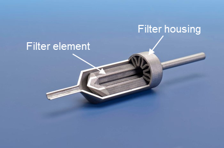
Figure 1 - Image of cross-sectioned advanced propulsion filter
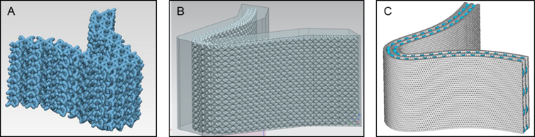
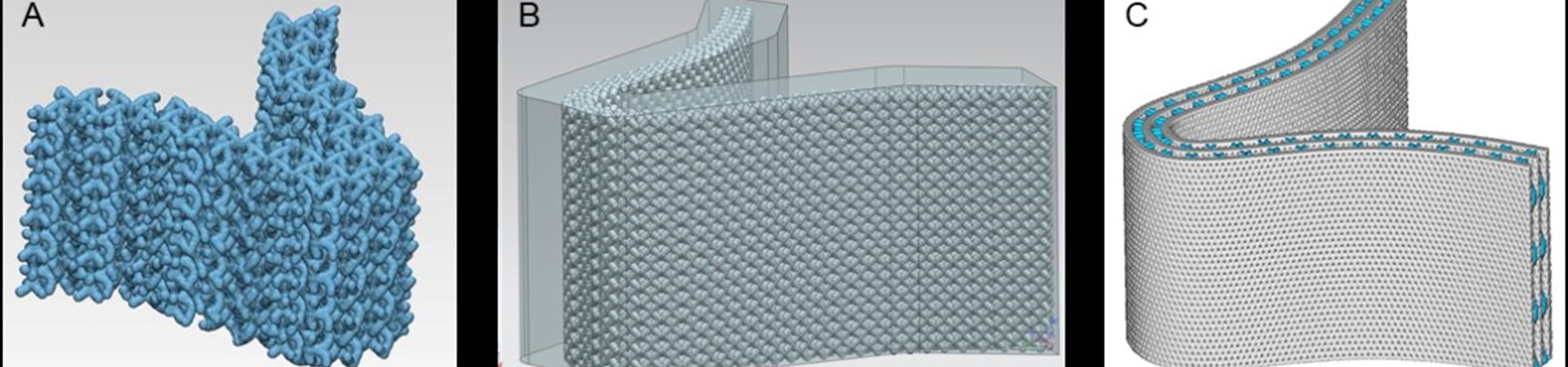
Figure 2 - Illustration of the three design approaches taken producing each of the samples.
Within the design aspect of filter development, complex unit-cell geometries or the use of stacked, offset layers are utilised in order to reduce orifice sizes as much as possible. Such intricate models can result in computational challenges such as file size handling and transfer. In order to get around this, various approaches have been taken including reduction of surface area by using hexagonal struts rather than cylindrical ones, direct slicing of parts and implicit modelling utilising state-of-the-art software.
Within the AM process itself, the use of fine titanium powder (PSD <7 µm) enables the LPBF process to produce parts at layer heights on the order of 10 µm (z-resolution) with similar resolution in x and y. This allows for accurate parts to be made that include the necessary stock material required in order for the parts to maintain accuracy after post-processing. The post-processing technology used allows for excellent control of material removal homogeneously from all surfaces including internal geometries.
Thus far, proof of concept work has been carried out that confirms pore sizes of < 100µm are achievable. To determine this, smaller sections of the filter were designed using 3 different unit cell/layering approaches (Figure 1). Upon manufacture and post-processing designs A and B were found to be the most suited to being manufactured via the micro LPBF process whilst also demonstrating a potential to be uniformly post-processed as to achieve the desired pore sizes. The uniformity of material removal was confirmed both externally via scanning electron microscopy (SEM) and internally via micro computed tomography (CT) (Figure 3).
Upon scaling up of designs A and B it was found that only design B could be scaled up because design A’s file sizes grew too large to be computationally processed within reasonable time-scales. Thus, the remaining development samples were fabricated using Design B. After fabrication of design B in the larger sample sizes de-lamination (Figure 4a) was observed in the largest of the three samples. Upon investigation it was discovered that this was caused by high oxygen content in the powder supply which 3D MicroPrint are currently trying to overcome. Unfortunately, this resulted in the final samples having to be reduced in size to ensure delamination did not occur so that testing of the filter could be conducted. Post-processing of the larger samples results in greater control over the process and a pore size of closer to 50 µm could be achieved (Figure 4c).
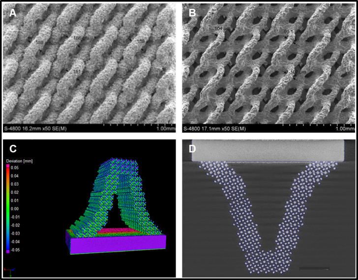
Figure 3: SEM images of design A before (A) and after post-processing (B). MicroCT data demonstrating the deviation of the produced part away from the designed CAD geometry both in 3D (C) and in 2D (D).
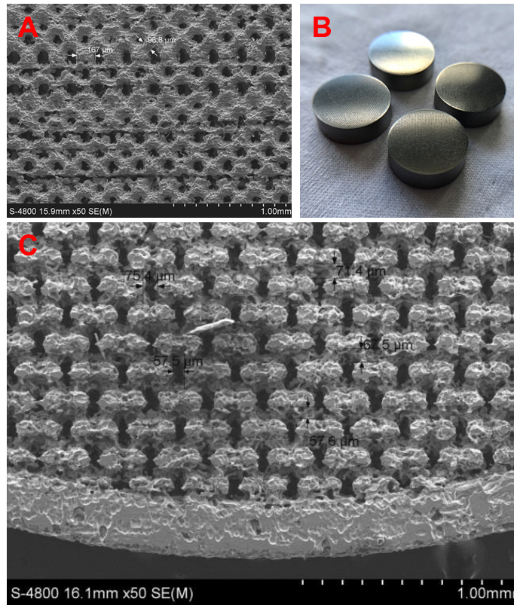
Figure 4 - Images demonstrating delamination (A), the final samples (B) and the final porosity achieved after further post-processing development (C)